Pre-Engineered TMT Reinforcement · Drawing-Led Preparation · Project-Specific Reinforcement · Coordinated Supplysales@indosonnic.com
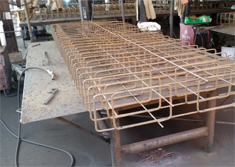
Beam cages assembled on a fabrication bench

Reference visual

Reinforcement Cages

Individual Bars. One Coordinated Assembly. A Better-Prepared Site.

Prefabricated reinforcement cages shaped around your approved drawings and construction sequence.

Bring reinforcement details together before they reach the workface. INDOSONNIC prepares reinforcement cages that combine specified main bars, stirrups, hoops, and links into organised assemblies for concrete construction.

From columns and beams to footings, piles, and custom structural elements, each cage is prepared around approved reinforcement requirements. Completing selected assembly activities before delivery can reduce repetitive site fixing and help teams organise material, handling, and placement.

Prepared as an Assembly. Planned for Installation.

A reinforcement cage must suit both its final position and the steps needed to get it there.

Our preparation approach considers reinforcement geometry, connections, transport, lifting access, and installation sequence. Depending on project requirements, cages may be supplied as complete units, partial assemblies, or identified segments.

The agreed scope defines what arrives assembled, which components are supplied separately, and what work remains at site.

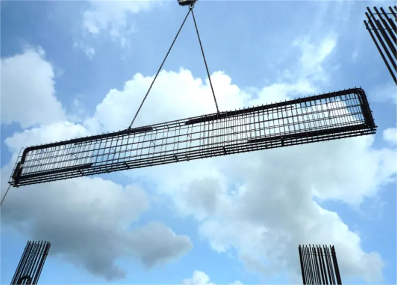
Beam reinforcement cage lifted into position
Reference visual

Sub-products

Types of Reinforcement Cages & Specifications

Reinforcement cages combine main bars, stirrups, hoops, and links into assemblies prepared for specific structural elements. INDOSONNIC reviews each requirement against approved drawings, manufacturing feasibility, and site handling arrangements.

Column Reinforcement Cages

Prepared reinforcement for vertical structural elements.

Column cages bring longitudinal bars and transverse reinforcement together in the approved arrangement. Supply may be planned as complete cages or segments to suit connections, transport, and erection.
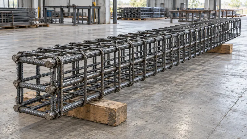
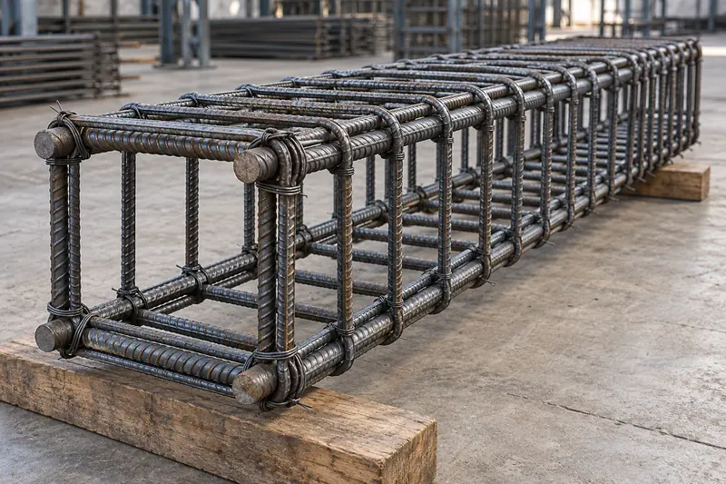
Column reinforcement cage lying horizontally
Product illustration
Square column cage end view with main bars and ties
Product illustration
ParameterSpecification
Cage configurationSquare, rectangular, circular, or approved custom geometry
Cross-sectional dimensionsAs per approved reinforcement drawings
Main barsDiameter, number, and arrangement as scheduled
Stirrups, hoops, and crosstiesShape, diameter, hooks, and spacing as detailed
Cage lengthAs agreed within manufacturing and handling limits
ConnectionsStarter bars, laps, or couplers as approved
IdentificationColumn mark, level, and segment reference

Beam Reinforcement Cages

Main bars and stirrups coordinated for placement.

Beam cages organise reinforcement around the approved beam details, including support zones, anchorage, and connections. Some bars may be supplied separately where installation access requires site completion.

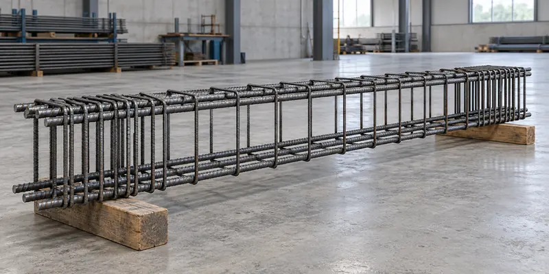
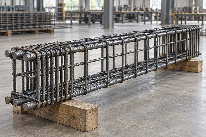
Full-length beam reinforcement cage on bearers
Product illustration
Beam cage on timber bearers showing bars and stirrups
Product illustration
ParameterSpecification
Cage configurationRectangular, grade beam, tie beam, or approved custom arrangement
Cage dimensionsLength, width, and depth as detailed
Main barsNumber, diameter, layers, and positions as scheduled
StirrupsDiameter, shape, and spacing by zone
Additional reinforcementIncluded or supplied separately, as identified
Anchorage and splicesAs per approved details
Joint interfacesCoordinated with columns, slabs, and adjoining beams
IdentificationBeam mark, level, location, and segment reference

Footing Reinforcement Cages & Assemblies

Organised reinforcement for individual and continuous foundations.

Footing reinforcement may be supplied as mats, partial assemblies, or complete cages where feasible. Preparation considers foundation geometry, reinforcement layers, column starters, and access for placement.

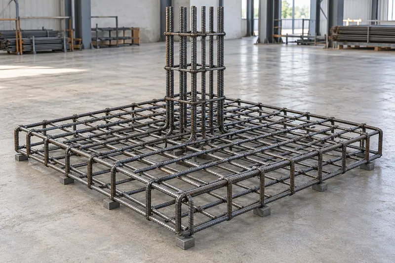
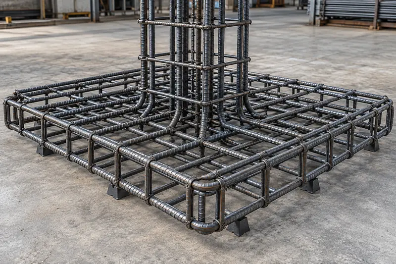
Footing assembly with starter bars on chairs
Product illustration
Footing mat with column starter bars
Product illustration
ParameterSpecification
Foundation typeIsolated, combined, or strip footing
Assembly dimensionsAs per approved footing reinforcement geometry
Main reinforcementBar diameters and spacing in each direction
Reinforcement layersBottom, top, and additional bars as detailed
Starter-bar interfaceAs per approved column or pedestal details
Supports and chairsType and supply responsibility as agreed
Assembly divisionsBased on approved details and handling requirements
IdentificationFooting mark, layer, and assembly reference

Pile Reinforcement Cages

Cylindrical assemblies planned for handling and lowering.

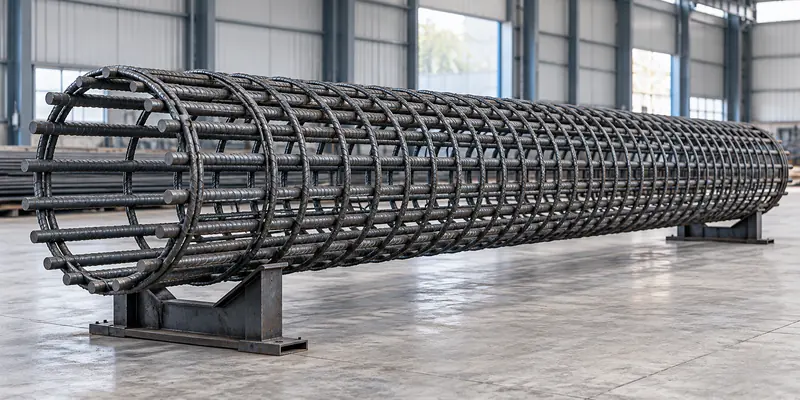
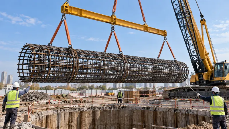
Pile cages combine longitudinal bars with specified rings or spiral reinforcement. They may be supplied in a single length or identified segments connected according to approved details.

Full-length circular pile cage on supports
Product illustration
Pile reinforcement cage lifted by crane using a spreader beam
Reference visual
ParameterSpecification
Cage configurationCircular or other approved geometry
Cage diameterAs per approved reinforcement dimensions
Cage lengthComplete length or planned segments, as agreed
Longitudinal barsNumber, diameter, and arrangement as scheduled
Transverse reinforcementRings or spiral, with specified diameter and spacing
Segment connectionsApproved laps, couplers, or other specified connections
Stiffening and lifting provisionsAs required by the approved handling arrangement
Spacers and accessoriesAs specified, with supply scope agreed
IdentificationPile type, cage mark, and segment sequence

Raft Reinforcement Assemblies

Coordinated components for multi-layer foundation reinforcement.

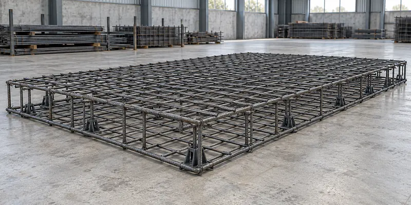
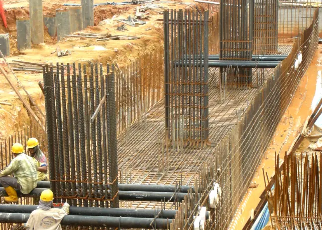
Selected raft areas can be reviewed for prefabricated mats or three-dimensional assemblies. Preparation must fit the complete reinforcement layout, including supports, column zones, openings, and placement sequence.

Two-layer raft reinforcement assembly
Product illustration
Raft reinforcement with column starters in an excavation
Reference visual
ParameterSpecification
Supply formatMats, partial cages, or selected prefabricated assemblies
Assembly dimensionsAs per approved layout and handling limits
Main reinforcementDiameter and spacing in each direction
Layer arrangementTop, bottom, and intermediate layers as detailed
Local reinforcementColumn zones, openings, edges, and other additions as specified
Supports and chairsAs designed, with supply responsibility agreed
ConnectionsLaps, couplers, and assembly interfaces as approved
IdentificationRaft zone, layer, direction, and assembly reference

Shear Wall & Boundary Element Cages

Prepared assemblies for wall reinforcement and concentrated reinforcement zones.

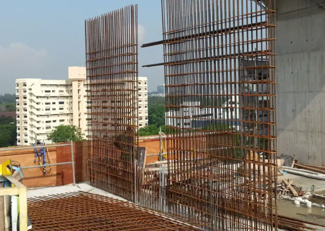
Wall assemblies coordinate vertical bars, horizontal bars, and specified confining reinforcement. Assembly boundaries consider openings, connections, congestion, and the formwork sequence.

Wall reinforcement panels standing at roof level on a building
Reference visual
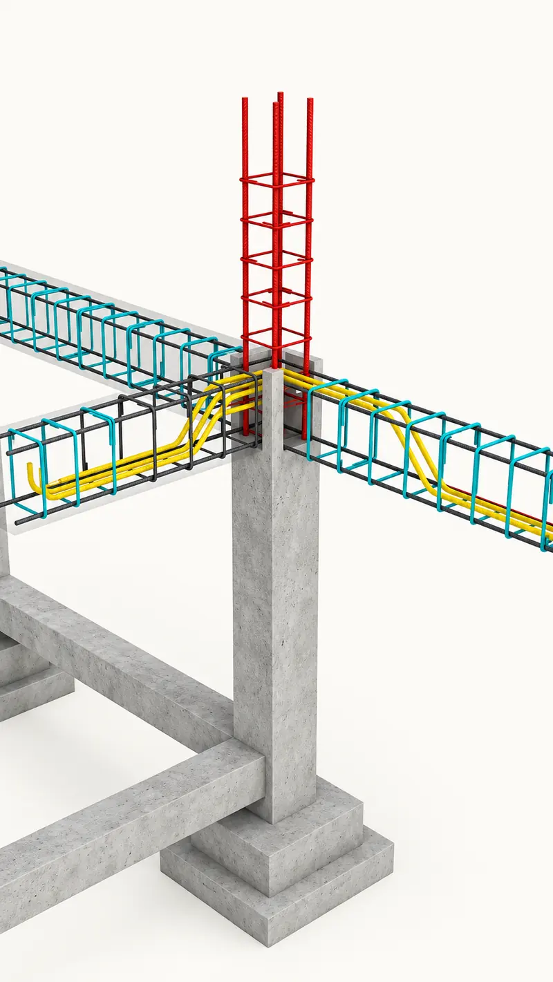
3D illustration of beam cages meeting a column cage
Concept illustration
ParameterSpecification
Assembly typeWall panel, boundary element cage, or partial assembly
Overall geometryAs per approved wall elevations and sections
Vertical reinforcementDiameter, number, spacing, and arrangement as detailed
Horizontal reinforcementDiameter and spacing as specified
Confining reinforcementLinks, hoops, and crossties as approved
Openings and connectionsCoordinated with approved local reinforcement details
Splices and couplersPositions and connection types as specified
IdentificationWall mark, level, boundary zone, and segment reference

Pedestal Reinforcement Cages

Compact assemblies for detailed foundation interfaces.

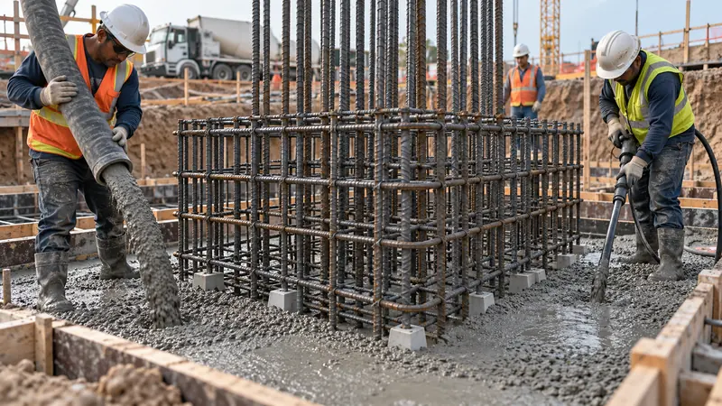
Pedestal cages organise longitudinal bars and links around approved foundation and upper-element connections. Preparation also considers clearances around anchor bolts or embedded items where applicable.

Concrete being placed around a prepared footing and column cage
Reference visual
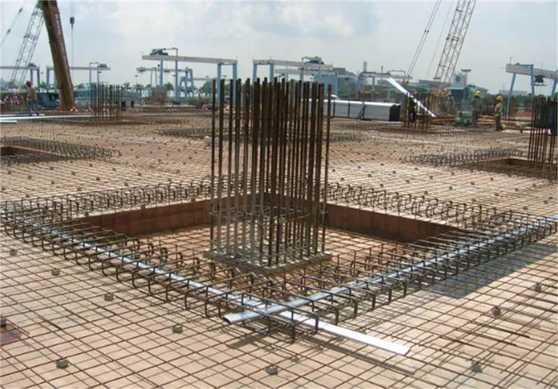
Footing reinforcement with column starter bars on site
Reference visual
ParameterSpecification
Cage shape and dimensionsAs per approved pedestal reinforcement drawings
Main reinforcementNumber, diameter, and arrangement as scheduled
Links and tiesDiameter, configuration, and spacing as detailed
AnchorageAs specified into the adjoining foundation or element
Interface clearancesCoordinated with approved anchor and embedded-item layouts
Cage heightAs detailed, within agreed handling limits
IdentificationPedestal mark and location reference

Custom Reinforcement Cages

Project-specific assemblies for specialised geometry.

Custom cages address reinforcement arrangements that do not fit standard categories. Feasibility is reviewed against the approved design, assembly access, transport, lifting, and installation requirements.

3D illustration of beam cages meeting a column cage
Concept illustration
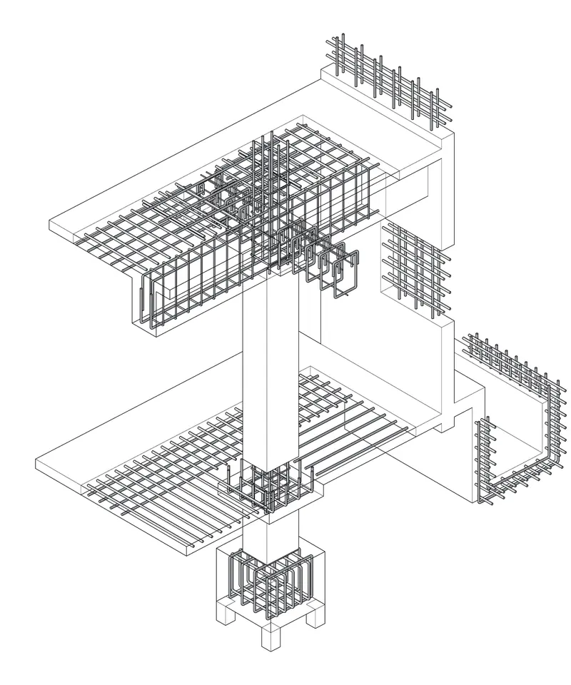
Line drawing of column, beam and footing cages at a junction
Concept illustration
ParameterSpecification
GeometryAs per approved, fully dimensioned drawings
ReinforcementBar sizes, quantities, shapes, and spacing as scheduled
Assembly boundariesDefined around connections and installation sequence
ConnectionsAs approved for the project
Embedded-item interfacesIncluded only within the agreed scope
Handling provisionsBased on the engineered handling arrangement
Inspection requirementsAs agreed for the assembly
IdentificationUnique component and segment references

Specification

Product Specifications

ParameterSpecification
Product formatPrefabricated reinforcement cage, partial assembly, or planned segment
ApplicationsColumns, beams, footings, piles, and approved custom structural elements
Cross-section and geometryAs per approved reinforcement drawings
Overall dimensionsBased on approved reinforcement geometry and specified concrete cover
Steel gradeAs specified and agreed for the project
Main reinforcementBar diameters, numbers, lengths, and arrangement as scheduled
Stirrups, hoops, and linksSizes, shapes, hooks, and configurations as approved
Reinforcement spacingAs detailed for each structural zone
Cage or segment lengthProject-specific, within agreed manufacturing, transport, and handling limits
Anchorage and bendsAs per approved detailing
Splices and couplersType, location, and supply scope as approved and agreed
Assembly methodTied; welded only where specifically permitted and approved
Additional reinforcementIncluded or supplied separately, as identified in the order
Dimensional tolerancesAs agreed under applicable project requirements
IdentificationElement mark, location, level, and cage or segment reference
Lifting and temporary stabilitySubject to an agreed engineered handling arrangement
Inspection and documentationAs defined in the project and supply scope
Supply modelMaterial supply with fabrication, or processing of customer-issued steel, as agreed
Measurement basisAs stated in the quotation
Delivery formatComplete cages, partial assemblies, or identified segments

Specification

Specifications Common to All Cage Types

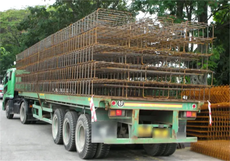
Prefabricated cages loaded on a trailer for transport (number plates and markings blurred)
Reference visual
ParameterRequirement
Steel gradeAs specified and agreed for the project
Bar diameter rangeConfirmed against manufacturing capability for each enquiry
Assembly methodTied; welded only where specifically permitted and approved
Concrete coverMaintained during installation as specified in approved drawings
Dimensional tolerancesAs agreed under applicable project requirements
Lifting and temporary stabilityAddressed through an engineered handling arrangement
DocumentationMaterial certificates, inspection records, and dispatch identification as agreed
DeliveryComplete units, partial assemblies, or identified segments
Site completionRemaining bars, connections, supports, and responsibilities defined before supply

Get Specifications for Your Project.

Share your approved drawings, bar bending schedule, quantities, material requirements, and delivery priorities for a cage-specific quotation.

Advantages

More Preparation Before Delivery.

  • Reduce repetitive site assembly by completing selected fixing activities in advance.
  • Organise reinforcement by location through agreed cage marks and identification.
  • Coordinate construction stages with planned assembly divisions and deliveries.
  • Clarify remaining site work by defining connections, loose components, and installation responsibilities.

The practical benefit depends on the design, quantities, repetition, logistics, and available handling equipment.

Prefabricated cages loaded on a trailer for transport (number plates and markings blurred)
Reference visual

From Approved Details to Prepared Cages.

  1. 01Share Drawings
  2. 02Confirm Assembly Scope
  3. 03Prepare Cages
  4. 04Check & Identify
  5. 05Coordinate Delivery

Checks may cover bar sizes and quantities, cage dimensions, spacing, connections, and identification within the agreed inspection scope.

Site placement must still address specified cover, supports, remaining connections, temporary stability, and inspection before concreting.

Standards

Indian and International Standards

Prefabricated Column, Beam and Foundation Cages

Indian references

  • IS 1786, IS 2502 and relevant IS 456 provisions.
  • IS 13920 where seismic detailing applies.
  • IS 9417 where reinforcement welding is specified and applicable.

International references

  • BS 8666 for scheduled and bent reinforcement.
  • ISO 17660-1 for load-bearing reinforcement welds, or ISO 17660-2 for non-load-bearing reinforcement welds, subject to scope.
  • AWS D1.4/D1.4M where specified for reinforcement welding within its scope.

Pile Reinforcement Cages

Pile cages follow the relevant reinforcement material, bending and connection requirements described above, together with the project’s pile design and construction specification.

Share Your Drawings. Let’s Bring the Details Together.

For a project-specific quotation, send:

  • Approved reinforcement drawings and bar bending schedules.
  • Cage types, dimensions, quantities, and location references.
  • Steel grades and bar diameters.
  • Anchorage, splice, and coupler details.
  • Required delivery stages.
  • Site access, unloading, lifting, and installation constraints.
  • Required material supply, fabrication, and documentation scope.

Share Your Drawings. Let’s Prepare What Comes Next.

Send your drawings, quantities, material specifications, project location, and delivery requirements for a project-specific quotation.